METAL-WORK -OBJ
01-10: ABACCDADAB
11-20: AACDDDCAAA
21-30: DBDDCABBBC
31-40: CABCABDCDB
COMPLETED!!!
METAL- WORK ESSAY- ANSWERS
(1ai)
DRILLING MACHINE:
(PICK ANY THREE)
(i) Wear appropriate personal protective equipment (PPE) to protect against flying debris and noise.
(ii) Secure the workpiece firmly before drilling to minimize the risk of it moving unexpectedly.
(iii) Always use the correct drill bit for the material being drilled.
(iv) Keep hands and fingers away from the rotating parts of the machine.
(v) Avoid wearing loose clothing or jewelry that could get caught in the drill.
(vi) Disconnect the power supply before changing the drill bit or performing any maintenance or repairs on the machine.
(1aii)
WELDING MACHINE:
(PICK ANY THREE)
(i) Wear appropriate PPE to protect against sparks heat and fumes.
(ii) Set up the welding machine in a well-ventilated area to prevent the build-up of harmful fumes and gases.
(iii) Ensure that the work area is clear of flammable materials.
(iv) Inspect the welding cables connectors and grounding before each use.
(v) Follow the manufacturer’s instructions for setting and adjusting the welding machine.
(vi) Allow the machine to cool down before changing electrodes.
(1aiii)
POWER SAWING:
(PICK ANY THREE)
(i) Always wear appropriate PPE to protect against flying debris noise and accidental contact with the saw blade.
(ii) Use the correct type of blade for the material being cut and ensure it is sharp and properly installed.
(iii) Secure the workpiece firmly before cutting.
(iv) Keep hands and fingers away from the path of the saw blade.
(v) Avoid wearing loose clothing or jewelry that could get caught in the saw.
(vi) Disconnect the power supply or lock out the machine before changing the blades.
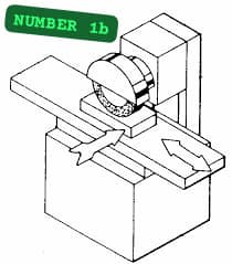
(1b)
Draw the diagram

Removing a high spot in a metal can be done through grinding. Carefully inspect the metal surface to identify the exact location of the high spot. Using a suitable work area with a sturdy workbench to support the metal piece and an appropriate grinding or sanding tool, begin grinding and frequently stop and inspect the surface to gauge the progress. Switch to finer grit sandpaper or grinding wheel when the high spot is removed to smooth out the surface. Apply a coat of paint or primer to protect the metal and improve its appearance.
••••••••••••••••••••••••••••••••••••••••••••••••••••••••••••••••••
(2ai)
Soldering is a process of joining two or more metal components together by melting and flowing a filler metal into the joint.
(2aii)
(i) Clean the surfaces: Ensure that the surfaces to be soldered are clean and free from dirt oxidation and other contaminants. Use a gentle abrasive such as sandpaper or a wire brush to remove any corrosion or oxidation.
(ii) Flux application: Apply a flux which is a chemical cleaning agent to the metal surfaces. The flux helps to remove any remaining oxides and promotes the flow of solder. Flux can be applied using a flux pen or dipping the soldering tip into flux paste.
(iii) Heat the joint: Use a soldering iron or a soldering station to heat the joint. The temperature should be sufficient to melt the solder but not excessively high to cause damage. The ideal temperature will depend on the type of solder and the materials being soldered.
(iv) Apply the solder: Once the joint is heated touch the solder wire to the joint and allow it to melt and flow into the joint. Ensure that the solder completely covers the joint and forms a concave shape.
(v) Remove the heat: Once the solder has flowed and formed a good joint remove the heat source from the joint. Allow the solder to cool and solidify naturally without disturbance.
(vi) Inspect the joint: After the joint has cooled visually inspect it to ensure it is properly soldered. The solder should form a shiny smooth and even coating around the joint. The joint should also be strong and have good electrical and thermal conductivity.
(vii) Clean the joint: If necessary clean the soldered joint using a soldering iron cleaning sponge or a soldering iron tip cleaner. This will remove any excess flux or solder residue and ensure a clean and professional-looking joint.
(2bi)
(PICK ANY FOUR)
(i) Vise
(ii) Clamps
(iii) Collets
(iv) Drill press vise
(v) Magnetic base
(vi) Jigs and fixtures
(vii) Workpiece clamping systems
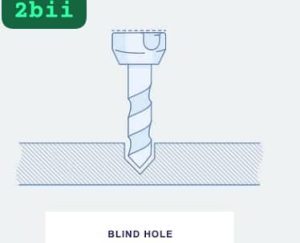
(2bii)
Draw the diagram

••••••••••••••••••••••••••••••••••••••••••••••••••••••••••••••••••
(4a)
(TABULATE)
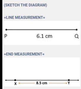
=LINE MEASUREMENT=
(i) Measurement is taken along a straight line.
(ii) Used to determine the length of a line
(iii) Measures the entire length of a line.
(iv) Accuracy depends on the measuring tool.
(v) Commonly used in carpentry, construction, and other linear measurements.
=END MEASUREMENT=
(i) Measurement is taken from one end to another.
(ii) Used to determine the distance between two endpoints
(iii) Measures from one end to the desired endpoint.
(iv) Accuracy depends on the precision of measurement.
(v) Commonly used in measuring distances and dimensions.
(SKETCH THE DIAGRAM)
=LINE MEASUREMENT=
=END MEASUREMENT=
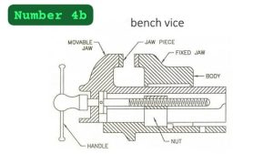
(4b)
Draw the diagram

••••••••••••••••••••••••••••••••••••••••••••••••••••••••••••••••••
(5ai)
Cutting speed is the speed at which the cutting tool or workpiece moves relative to each other during a machining operation. It determines the rate at which material is removed.
(5aii)
Spindle speed is the rotational speed of the spindle, which holds and drives the cutting tool during a machining operation. It specifies how fast the cutting tool rotates, influencing the cutting speed and the material removal rate.
(5aiii)
Feed is the rate at which the cutting tool or workpiece moves per revolution or per unit of time. It shows how quickly the cutting tool advances into the workpiece, resulting in material removal.
(5b)
Given:
Cutting speed = 200 m/min
Diameter = 28 mm
Spindle Speed (RPM) = (Cutting Speed x 1000) / (π x Diameter)
Spindle Speed (RPM) = (200×1000)/(π x 28)
Spindle Speed (RPM) = 200000/(3.14×28)
Spindle Speed (RPM) = 2271.67 RPM
••••••••••••••••••••••••••••••••••••••••••••••••••••••••••••••••••
(7a)
(TABULATE)
(i) In draw filing the file is used in a long smooth uninterrupted stroke along the length of the workpiece. While In the cross filing, the file is used in a crisscross motion moving the file back and forth in alternating directions.
(ii) Draw filing is used to create a smoother and finer finish compared to the cross filing. The long smooth strokes of draw filing help to eliminate irregularities and produce a more polished surface.
(iii) Cross filing is more effective in removing material quickly and efficiently compared to draw filing. The back and forth motion of the file in cross filing allows for faster material removal making it suitable for rough shaping or removing larger amounts of material.
(iv) Draw filing requires more precision and control as the file must be held at a consistent angle and pressure along the workpiece. Cross filing on the other hand allows for more aggressive and rapid filing.
(v) Draw filing is used for final finishing and smoothing of surfaces such as in woodworking or metalworking to achieve a desired level of smoothness. While Cross filing is used in initial shaping and removal of material such as in rough carpentry or metal fabrication.
(7b)
Draw the diagram

(7c)
(PICK ANY THREE)
(i) Lubrication
(ii) Cooling
(iii) Chip evacuation
(iv) Rust prevention
(v) Surface finish improvement
(vi) Tool life improvement.
COMPLETED!!

Leave a Reply